Product Features
* Measures AC, DC and pulsed signals.
* Excellent accuracy, good linearity.
* Strong resistance to external interference, high common mode rejection ratio.
* Low temperature drift, low power consumption, wide frequency band.
* Split structure, easy to install.
Product Application
* AC frequency conversion speed regulation.
* Servo motor traction.
* Uninterruptible power supply(UPS).
* Welding machine, battery power supply.
Download Size Sheet
 TR0214-LKH.pdf
Product Parameters
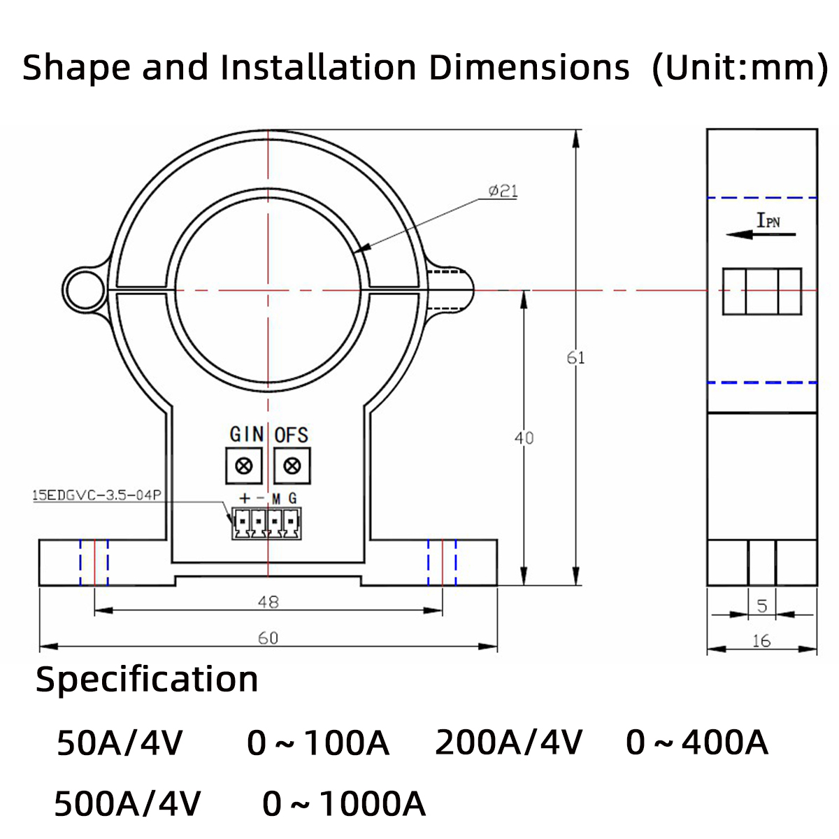
| Specification | 50A/4V | 200A/4V | 500A/4V | Unit |
IPN | Primary Rated Input Current | 50 | 200 | 500 | A |
IP | Primary Current Measurement Range | 0-100 | 0-400 | 0-1000 | A |
VSN | Secondary rated output voltage | 4 | V |
VC | The Power Supply Voltage | ±12-15(±5%) | V |
IC | Current Consumption | <25 | mA |
Vd | Insulation Voltage | Between primary and secondary circuits:2.5kV/50Hz/1min |
|
εL | Linearity | <1 | %FS |
X | Precision | TA =25℃:≤±1 | % |
V0 | Offset Voltage | TA =25℃:≤±20 | mV |
VOM | Magnetic Offset Voltage | IP=0 after 3*IPN:≤±20 | mV |
VOT | Offset Voltage Temperature Drift | IP =0 TA =-40-+80℃:≤±1 | mV/℃ |
Tr | Response Time | ≤5 | μS |
f | Bandwidth(-3dB ) | DC-20 | KHz |
TA | Working Temperature | -40-+80 | ℃ |
TS | Storage Temperature | -45-+85 | ℃ |
RL | Load Resistance | TA =25℃:≥10 | kΩ |
Structure and Dimension
Circuit link Diagram
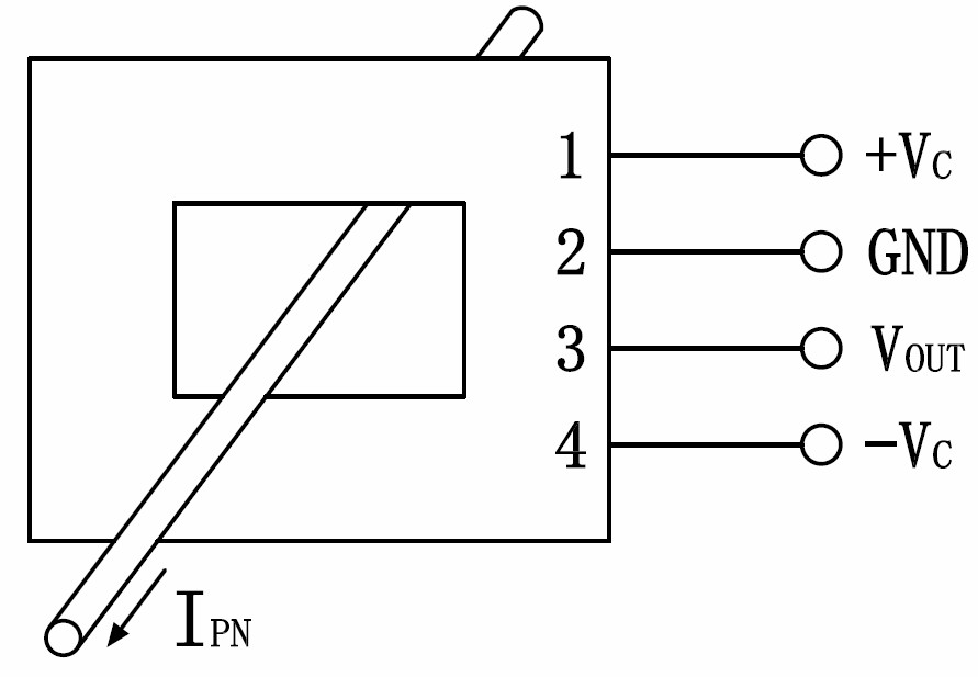
Notes:
IPN:Primary current input direction
+ :Positive 12V/15V power supply
- :Negative 12V/15V power supply M :Secondary signal output
G :Power ground OFS:Zero adjustment GIN:Amplitude adjustment
Installation Precautions
* The sensor should be wired correctly, otherwise it may damage the internal components of the sensor.
* Dynamic performance (di/dt and response time) is best when the input current row is fully filled with the primary perforation.


