Product Overview
High Precision Current Sensors are advanced devices designed to measure AC and DC currents with exceptional accuracy and stability. They convert the current into a proportional electrical signal for precise monitoring, control, and protection. Using technologies such as Hall effect, fluxgate, or zero-flux methods, these sensors achieve high linearity, low offset drift, and fast response. They are widely used in power electronics, renewable energy systems, smart grids, industrial automation, and electric vehicles. With strong anti-interference capability, wide bandwidth, and compact design, high precision current sensors ensure reliable performance in demanding applications requiring accurate and consistent current measurement.
Product Features
* Tiny misaligned currents.
* Superior linearity.
* High isolation withstand.
* Small error between input & output.
* Wide Frequency bandwidth.
* Fast response speed.
* high-resolution.
* Low temperature drift.
Product Application
* New energy detection.
* Substitute hall products.
* Power electronic measurement.
* Industrial control and measurement.
* Medical facility.
* Standard for laboratory testing.
* Motor traffic.
* Instrument and meter.
Product Parameters
Type | Symbol | Test condition | Min | Rated | Max | Unit |
Measuring Range | IPM |
| -- | ±1000 | ±1200 | Adc |
Power Supply | Vc | Full range | ±14.5 | ±15 | ±15.5 | Vdc |
Current Consumption | Ic | Within the IPM range | ±40 | ±710 | ±840 | mA |
Ratio | KN | Input:Output | 1500:1 | -- |
Rated Output Current | ISN | Primary rated current | -- | ±666.7 | -- | mA |
Measuring Resistance | RM | Refer to Pic.1 | -- | 1.5 | 3 | Ω |
Precision | Xe | 25±10℃ | -- | -- | 0.02 | % |
Linearity | εL | -- | -- | -- | 20 | ppm |
Temperature Drift Coefficient | TCIOUT | -- | -- | -- | 0.1 | ppm/K |
Zero Offset Current | Io | 25±10℃ | -- | -- | ±5 | uA |
Zero Offset Current | IoT | Full operating temperature range | -- | -- | ±10 | uA |
Ripple Current | In | DC-10Hz | -- | -- | 2 | uA |
Dynamic Response Time | tr | 5% up to 90%IPN | -- | -- | 1 | us |
di/dt Accurately Followed | di/dt | -- | 200 | -- | -- | A/us |
Frequency Bandwidth(- 3 dB) | F | -- | 0 | -- | 100 | kHz |
Note: The rated current is rms current when measuring AC
 General Characteristic
Type | Symbol | Test condition | Min | Nominal | Max | Unit |
Operating Ttemperature Range | TA | -- | -40 | -- | +85 | ℃ |
Storage Temperature Range | TS | -- | -55 | -- | +100 | ℃ |
Output Sstatus Indication Signal | -- | When the output status indicator light (green LED) is on, it means that the product works normally, and the input current of the busbar does not exceed its bearing capacity; When the output status indicator light is off, it indicates that the product is not working properly or the input current value of the busbar is beyond its capacity. |
Security Feature
Type | Symbol | Test condition | Min | Nominal | Max | Unit |
Isolated Voltage Withstand | Between the primary and secondary | Vd | 50Hz,1min | -- | 2.5 | -- | kV |
Transient Isolation Withstand Voltage | Between the primary and secondary | Vw | 50us | -- | 5 | -- | kV |
Application Connection and Description
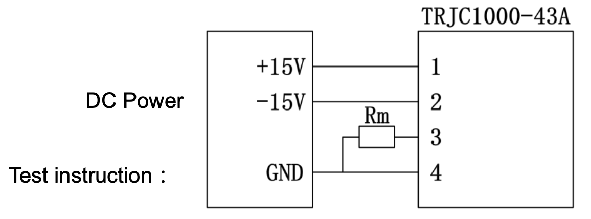
Pin definition
Terminal | 1 | 2 | 3 | 4 |
Definition | +15V | -15V | Iout | GND |
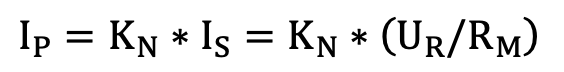
By measuring the test current IS flowing through Rm, or the voltage UR at both ends of Rm, the original side current IP can be obtained:
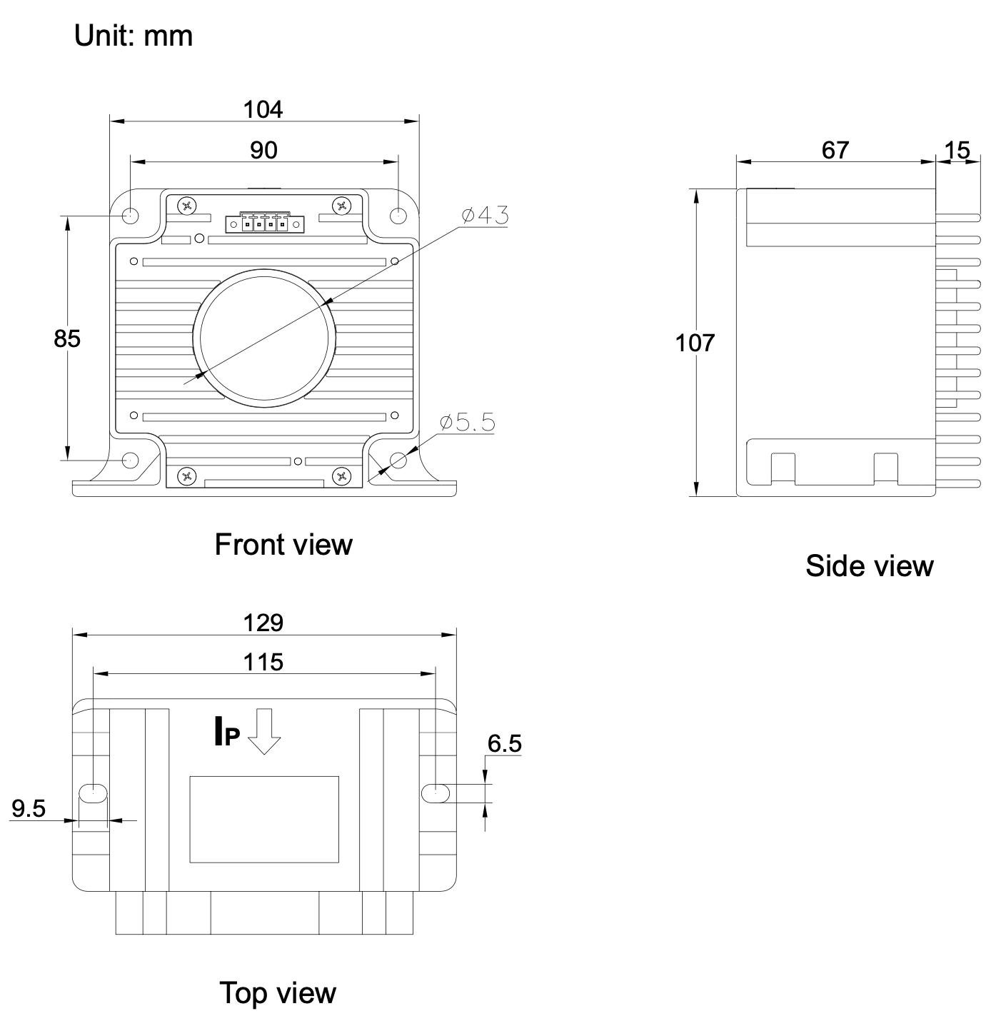
This product is molded part, PC material, tolerance of shape and dimensions in accordance with GB/T14486-2008 MT6.
Terminal output type, connected to 2EDGKM3.81-4P terminal.