- All
- Product Name
- Product Keyword
- Product Model
- Product Summary
- Product Description
- Multi Field Search
Views: 0 Author: Site Editor Publish Time: 2025-10-13 Origin: Site


1. Introduction
In electrical measurement and monitoring systems, both Current Transformer (CTs) and Current Transmitters are essential devices used to sense, measure, and convert electrical current. However, while these two components are related, they perform different functions and are used in different stages of current measurement and control.
A Current Transformer is primarily a sensing and scaling device, whereas a Current Transmitter is a signal conversion and output device. Understanding their differences is crucial in designing accurate and safe current monitoring systems for industrial, commercial, and power distribution applications.


A Current Transformer (CT) is an instrument transformer used to measure alternating current (AC). It steps down high primary current to a proportionally lower secondary current, making it easier and safer to measure by standard instruments such as meters or relays.
The CT operates on the principle of electromagnetic induction. The primary winding carries the load current, and the secondary winding is connected to measuring instruments or protective relays. The alternating magnetic flux produced in the core induces a proportional current in the secondary winding.
High accuracy and linearity
Suitable for high current measurement (up to thousands of amperes)
Requires external measuring circuit (meter or relay)
Passive device – no power supply required
Mainly used for AC measurement
Power system metering and protection
Energy monitoring in substations and switchgear
Motor and generator protection
Overcurrent and ground fault detection
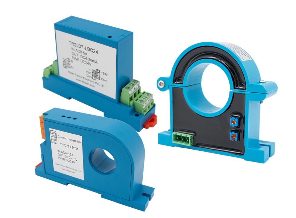
A Current Transmitter, sometimes called a current transducer, converts the measured current into a standardized output signal, typically 4–20 mA or 0–5 V / 0–10 V, which can be directly read by control systems, PLCs, or data acquisition modules.
Working Principle
A Current Transmitter usually contains a current sensor (such as a CT or Hall Effect sensor) combined with signal conditioning electronics.
The internal sensor detects the primary current.
The signal is then converted into a proportional voltage.
The signal conditioning circuit scales and converts it into a standardized analog output (e.g., 4–20 mA).
Some models also provide isolation, linearization, and digital communication (Modbus/RS485).
Provides standard analog or digital output
Works with both AC and DC current (depending on type)
Requires an external power supply (typically 12–24 VDC)
Compact and easy to integrate with control systems
High electrical isolation for safety
Energy management and building automation systems
Industrial process control and monitoring
Renewable energy systems (solar, wind inverters)
Electric vehicle charging infrastructure
Motor speed and torque monitoring
| Feature | Current Transformer (CT) | Current Transmitter |
|---|---|---|
| Function | Steps down high current for measurement or protection | Converts current to standard signal (4–20 mA, 0–10 V) |
| Output | Secondary current (1A or 5A) | Analog or digital signal |
| Measurement Type | AC only | AC or DC (depending on type) |
| Power Requirement | Passive (no external power) | Active (requires power supply) |
| Signal Processing | No signal conditioning | Includes signal conditioning and isolation |
| Integration | Connects to ammeter, relay, or protection device | Connects to PLC, controller, or monitoring system |
| Accuracy Class | 0.1–1.0 typical | 0.2–0.5 typical |
| Use Case | Power metering and protection | Process monitoring and control |
| Examples | Busbar CT, Split Core CT, Toroidal CT | DIN-rail Current Transmitter, Hall Effect Transmitter |
A Current Transmitter can be considered an upgraded form of a Current Transformer because it often uses a CT as its sensing element internally. However, the transmitter adds electronics that make the signal readable by automation systems.
In many installations:
The CT is used for power protection (e.g., in switchgear).
The Current Transmitteris used for monitoring and control (e.g., in building energy systems or industrial panels).
Thus, they complement each other within modern electrical measurement systems.
Use a Current Transformer when:
You only need to step down current for traditional meters or relays.
The system measures AC current only.
Cost and simplicity are priorities.
Use a Current Transmitter when:
You need a standardized signal for PLC or remote monitoring.
Both AC and DC currents need to be measured.
Isolation, accuracy, and real-time control are critical.
While both devices measure electrical current, their roles differ significantly in function and application.
A Current Transformer acts as a sensor and isolator, converting large currents into measurable smaller currents, while a Current Transmitter serves as a signal interface, transforming the measured current into a control-friendly signal.
Together, they form the foundation of modern electrical measurement, automation, and energy management systems, ensuring both safety and precision.